


This is the final part of this 3-part blog post, there is a possibility that in the future we may continue with adding further modifications and improvements but they will be published on separate blog posts.
Furthermore, if you haven’t already checked out part 1 and 2, we encourage you to check these out at the following links:
Part 1: http://lookuga.com/post/reverse-engineering-the-krups-piccolo-part-1
Part 2: http://lookuga.com/post/reverse-engineering-the-krups-piccolo-part-2-teardown
So let’s get on with the final post. I would like to start by mentioning that we wanted to challenge ourselves by allocating a budget of just 10 euros to design and build a replacement mainboard. After a couple of minutes we had our part list ready and a couple of minutes later we also found the required parts which we are also sharing with you below:
Part list
- 5V Relay x2
- TVR
- Transistor x2
- Diode x2
- Routing Wire
- ATmega168 or equivalent with internal pull-up resistors (Arduino Pro Mini)
- Resistor for switch (10k)
- 5v Power Supply
- Various Parts from the broken Krups Machine
The brains for this mainboard is the ATMEGA168, although we could have used the Atmel Studio to develop on it, we decided to stick with the Arduino Framework, as we thought it might be easier for beginners to use and experiment upon.
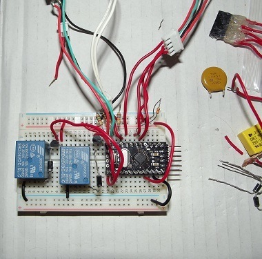
Once we had a working prototype built on a breadboard the next step was to shrink it to fit on a protoboard with the maximum size of 9.4 CM X 5.1 CM with all components and wiring routing.
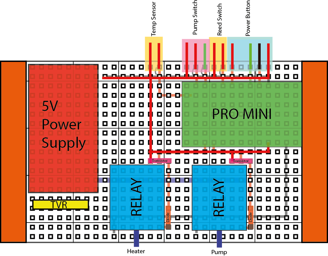
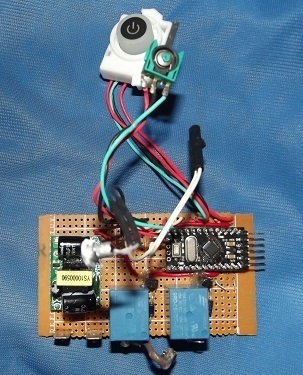
(the TVR is missing from this photo, but should be soldered between the live and natural)
All of the designs and code is licensed under GPL, so you are free to build your own with improvements as long as you release them back to public for free.
As stated earlier, other improvements or modification could be done, which include:
- WIFI Enabled - Make a coffee from your mobile
- Factory Printed PCB - Product designed PCB instead of the Protoboard
- Solid State Relays with built-in snubbers - smaller footprint, quieter and more reliable than mechanical relays
If anyone, does decide to build one for themselves or would like to get a built one, let us know on facebook!
GitHub Link for source code and design:
https://github.com/lookuga/DolceGusto
ProtoBoard.ai
Contains multi-layer illustrator file, broken down (pcb, top wiring,bottom wiring, components etc)<br
KrupsPiccolo_OpenSource.ino
Contains the source code for the microcontroller
Instructions to Use
- Connect power to coffee machine
- Should start pulsing green
- On pressing the power button, should turn to yellow (means heating up)
- Once heated up should turn to solid green
- On switch to start pump, it should start to pump water (either hot or cold) and should be yellow (heating while pumping)
- Show red, if the capsule holder is not detected when trying to start pump